Reverse Engineering the Arturia KeyStep Firmware
In this post, I document the steps I took to modify the stock firmware of an Arturia KeyStep keyboard.
Contents
- The Problem
- Teardown
- Firmware
- Initial Disassembly
- Memory Structure
- File Metadata
- Final Disassembly
- Reassembly
- Final Thoughts
The Problem
The Arturia KeyStep is a small MIDI keyboard with a set of buttons that allow you to shift the octave up or down. These buttons blink when the octave is currently shifted, with faster blinking meaning more of a shift.
Why is that is a problem? First of all, it’s hard to convey in video form how bright these LEDs are.1 Worst of all, the rate of flashing isn’t connected to anything musical, which means the sequencer can be set a certain tempo and the octave buttons will happily continue flashing to their own beat (which appears to be a subdivision of a second). Which causes:
It’s like when two car alarms are going off and they just. can’t. get. in. time. Except now it’s flashing lights in your face while trying to make music. I’m probably just too closed-minded to be able to achieve this polyrhythmic enlightenment, but I’m not the only one who has had an issue. Luckily, we can put off getting better at music by tackling this mundane issue in depth!
There are some low tech solutions to consider. The buttons could be covered with paint or tape or the LEDs themselves desoldered from the board, but it would be nice to still have a visual clue for when the octave is not the default. Also, when the “shift” button is held down, these same LEDs display different information that we would still like to be able to see.
So, first things first: let’s take it apart and see if we even have a chance of fixing it in software.
Teardown
My go-to for this situation, IFixit, doesn’t appear to have to have any teardowns posted for Arturia products, so let’s grab a screwdriver2 and get to work!
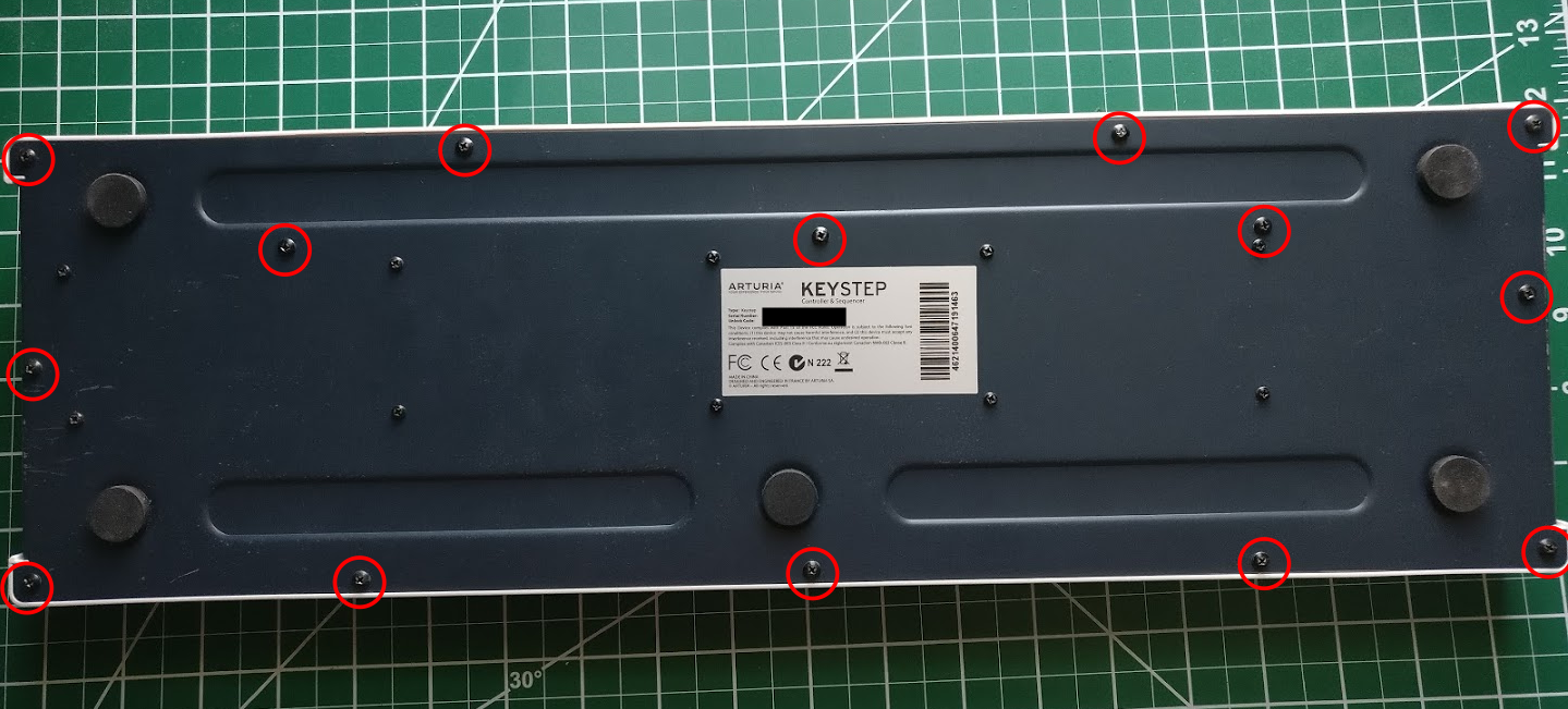
Getting this thing apart is actually quite user friendly: there are 14 Phillips-head screws on the bottom to remove.
After that, the top can be lifted off and unfolded.
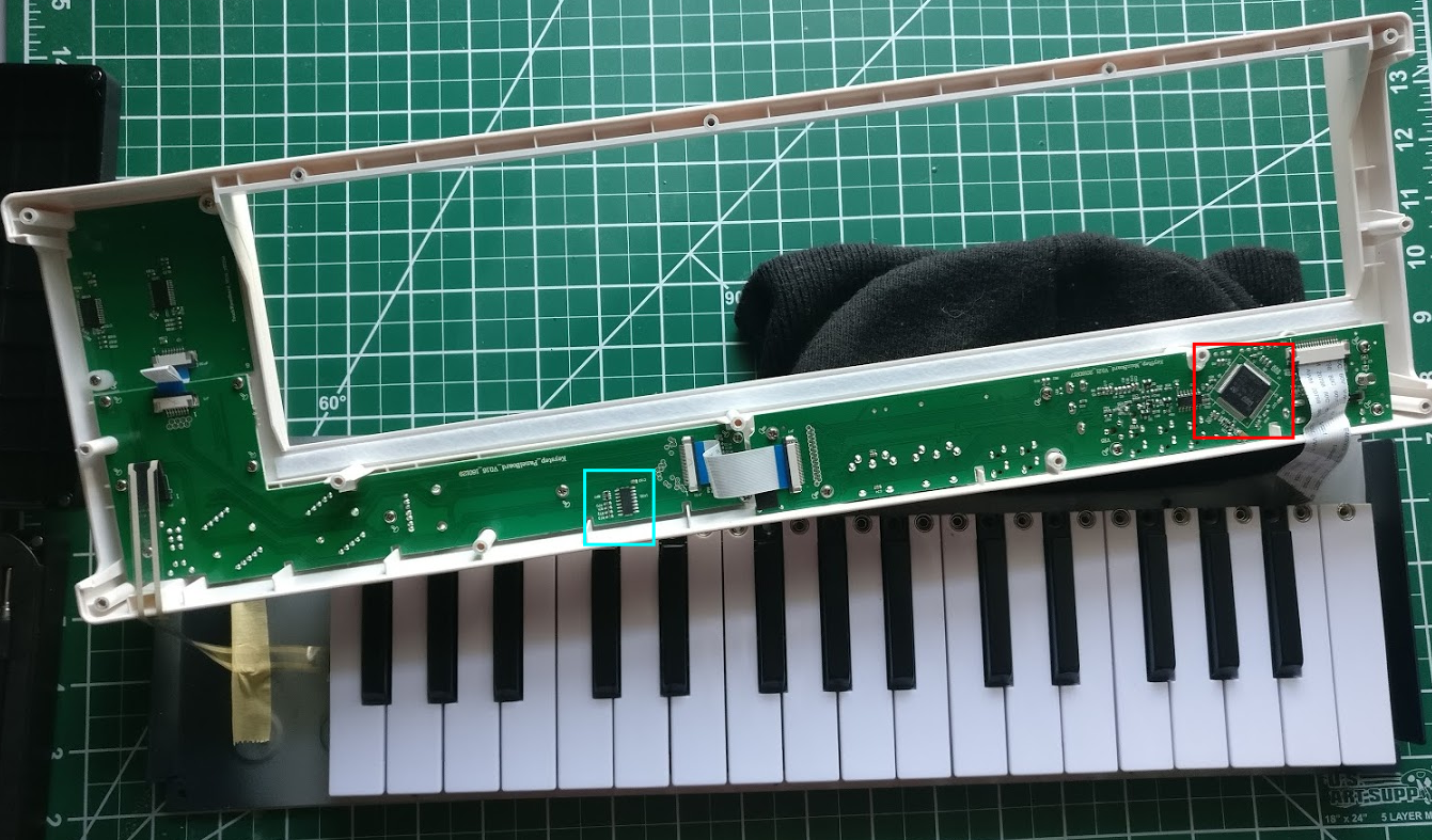
We can now identify the important components of the internal circuitry. The octave lights are attached on the bottom of the board on the left side of the image. I followed the traces with a multimeter, and found that all of the LEDs were attached to the chip marked by the cyan square. On the right side, we find the main processor of the keyboard (marked by the red square). The LED chip is connected via the ribbon cable in the middle. Let’s take a closer look at these two locations.
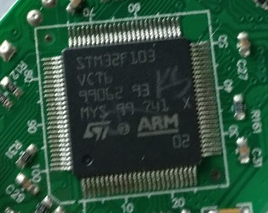
From the markings on the outside read STM32F103 and VCT6, which is an ARM 32-bit Cortex-M3
CPU. The datasheet can be found here,
and this appears to be the “LQFP100” package version. I’ve had a passing experience with ARM
development with the Particle Photon,
which hopefully means that this won’t be too difficult to deal with.
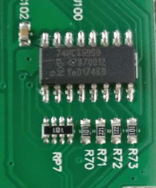
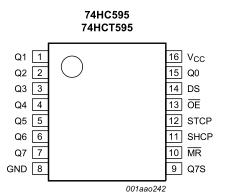
The other chip is a bit more difficult to read; the top line is 74HCT595D, which is a shift
register produced by NXP. The datasheet can be found here. This component holds the 8
bits that control the on/off state of the LEDs. When the lights need to change, a new 8 bits are
shifted into the register from the main processor.
Some more work with the multimeter confirms this is the case. Lights that are off are held high to
4.5 V on their respective pins. In particular, the “Octave -“ light is controlled by the bit
labelled Q4 on the datasheet, and the “Octave +” light is connected to Q3. We can then trace the
pins marked DS (for serial data input) and SHCP (for shift register clock input) to their
respective pins on the microcontroller. A use of a shift register means that many of the pins are
saved on the main processor, as well as making it easy to add more lights:3 simply add a larger
register or perhaps a sub-processer if it is needed.
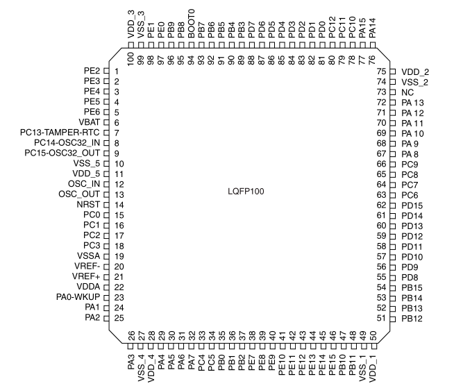
We find that the data line is connected to the pin marked PB15 and the clock is nearby on pin
PB13. There are multiple overlapping functions per pin on this chip, which can be found in the
datasheet under “pin definitions”. In this case, the most logical functions are SPI2_MOSI and
SPI2_SCK, respectively. This is a Serial Peripheral Interface, which can directly control a
shift register.
That’s just about all we need to know from the hardware side: how the data is handled and through which pins. We have a couple of options for what to shoot for during the software modification:
-
We can disable the light entirely for non-shift mode. This is similar to physically disabling the lights, but we still have the ability to see the other information.
-
We could alter the timer so that the octave lights flash much slower or stay on constantly.
-
We could attempt to synchronize the timer with the metronome clock. However, this would likely be difficult because of the extra state involved in knowing when it is started and stopped. Additionally, this is a functional keyword when the clock isn’t synced, so we would need one of the above as a fallback anyways.
-
We could also try to flash the light on and off much faster to get different persistent brightness effect, though this would depend on how the UI updates within the firmware.
Firmware
Now that we have the physical hardware sorted, let’s see what we can do with the firmware. Each
version is hosted on Arturia’s Website as a
“.led” file. I used the version marked as 1.0.1.15 for this step. Taking a look in a hex
editor, we see
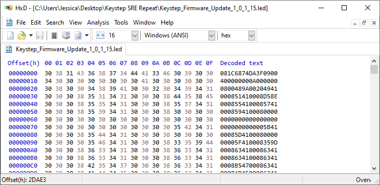
Ah! It’s already hex encoded. My initial guess is that this has something to do with the update mechanism working over MIDI SysEx messages. When the keyboard is in update mode, then it just has to decode the string and put it into the correct location in flash memory. Let’s get to work on a python script that will handle the intermediate formats:
fname = "Keystep_Firmware_Update_1_0_1_15.led"
with open(fname, "r") as f:
    with open(fname + ".bin", "wb") as out:
        line = f.readlines()[0]
        chunk = bytes.fromhex(line)
        print("{} bytes found".format(len(chunk)))
        out.write(chunk)
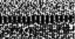
One of the more fun tricks for exploring binary data is to pack it into an image:
from PIL import Image

im = Image.frombytes("L", (64, len(chunk) // 64), chunk)
im.save(fname + ".bin.bmp")
This allows you to quickly scan over portions of the file and pick up patterns like groups of aligned values, blocks of continuous values, or sections with limited ranges of values. For instance, at the top of the file, we see

Groups of aligned data padded by zeroes, usually an array/table of some sort. Near the center, we have another one:
And lastly near the end of the file we have:
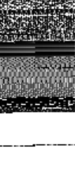
A couple of smooth gradients of grey (successively increasing values), a much bigger section of
lighter grey (implying more middle bytes where ASCII lives, i.e. a string table), and finally ending
with a solid chunk of mostly white (FF).
This is good news! If the firmware were encrypted (with the key baked into the microcontroller’s memory), then this would be completely unstructured random noise. With things the way they are now, we can take a pass at performing the disassembly.
Initial Disassembly
Ghidra is an open source reverse engineering tool released by the NSA in April 2019. IDA Pro also has a freeware version, but that only performs disassembly on Intel opcodes, not ARM.
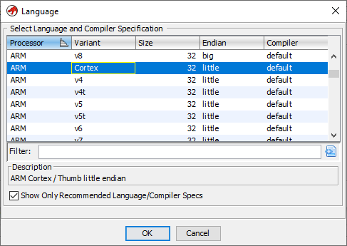
First, install and launch Ghidra using your preferred method, create a new project, and then drag the binary file we created into the project folder. It’ll take some time processing the file then we’ll have to select the language. From the datasheet, we want “ARM cortex little endian”:
It’ll chug a little bit more, then we can open the file in code browser, which will then prompt us to analyze the file:
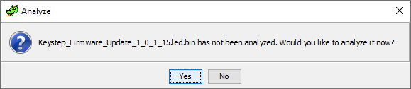
After starting the analysis, we come up with a lot (153) of errors, but it also managed to process a fair bit of the assembly. If we take a look at the symbol tree on the left hand side:
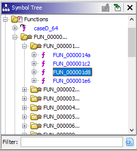
We see that it found many functions, quite a few of which are complete. We have some bonafide ARM assembly here!
I want to take a few minutes here to talk about how this whole process works. The actual firmware is the binary code that executed by the processor, meaning that it will get loaded into memory and then ran as a sequence of opcodes according to the ARM spec.4 All of the labels, function names, comments, etc. have long been stripped out.
What the disassembler does is match turn the binary form back into human readable opcodes by
reversing that same spec. However, since opcodes can be variable in length, a string of bytes can
mean any number of things depending on where you think the opcode started. There are not only
instructions in memory, but non-executable data as well. The disassembler handles this by making
some educated guesses and then following the execution flow. For instance, if a b (branch)
instruction is found pointing at some memory location, then it can start decoding opcodes at that
point and spread out to all the reachable parts of the program.
Additionally, functions follow a procedure call standard that defines how to use the registers to store arguments and pass return information and control flow back to the callee. The disassembler can match on these parameters to break up a program into its constituent functions. The toolkit generates C code in a similar way, by matching particular operations on registers and memory to what it would look like before the compilation occurs.
Lastly, all these recovered references and functions are given a generic name by the disassembler, but can be renamed with our own labels. As we untangle what pieces of the program do, then mark our progress and have it propagate through the code. The same is true of data types: if we identify a particular structure, then we can turn ugly offset references into nice structured references.
We still have quite a few problems that need fixing before continuing with the disassembly. All pointers in this architecture should be word-aligned (4 bytes), and instructions should be aligned to 2 bytes, which doesn’t appear to be the case half the time. Functions not ending on a word boundary are normally padded with zeros, but we are seeing the opposite of that as well. Finally, some functions appear to be misaligned and reference the middle of already referenced pointers and also branch to middle of instructions.
Memory Structure
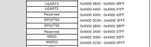
Let’s use what we know about how the memory structure of the problem should behave to clean up some of the errors in the disassembly. In ARM-land, the program data, random access memory, and peripherals are all referenced in one continuous memory space. Accessing functions of the chip and external pins are a matter of reading or writing to particular memory locations. Since we are interested in what code is talking to the LEDs, then we should be able to find it in the firmware through that specific pin’s address.
The useful addresses are defined in C code in ST’s Standard Peripheral Libraries. In
particular, we can look at the one that matches our chip: STM32F10x_StdPeriph_Lib_V3.5.0. The
header file gives us the base addresses that we are looking for (stm32f10x.h:1272):
#define FLASH_BASE            ((uint32_t)0x08000000) /*!< FLASH base address in the alias region */
#define SRAM_BASE             ((uint32_t)0x20000000) /*!< SRAM base address in the alias region */
#define PERIPH_BASE           ((uint32_t)0x40000000) /*!< Peripheral base address in the alias region */
At the very least we know that our first memory location should be greater than 0x08000000
(FLASH_BASE) as the whole thing has to be written to flash memory. Ghidra starts the program at
address 0x0 by default. FLASH_BASE is likely where the bootloader lives, as seen in this
excellent diagram that I shamelessly stole from here:
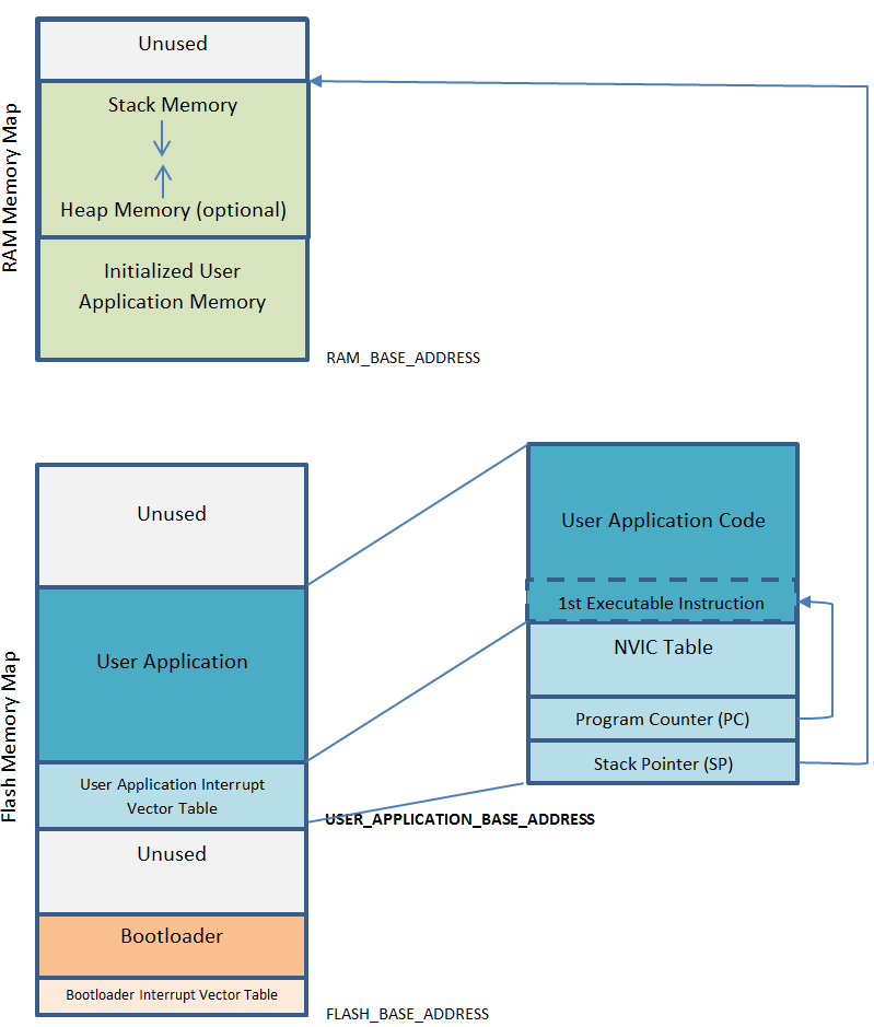
The program should begin with what is known as a vector interrupt table. Essentially this is a
list of memory locations to transfer control flow to under certain external conditions, like clock
ticks or faults. This is the structured memory we previously saw in bitmap form. The first element
in this table is the initial value of the master stack pointer. This is the pointer associated
with the push and pop instructions and is modified on every function call. This must be in a
location within SRAM.
After that, we have the initial value of the program counter, which is incremented after each statement and modified on a branch. This memory address is the entry point to the main program.
Going back to the hex editor, we don’t even see anything that could point to SRAM until hex offset 12 (remember it’s backwards because of little-endian):
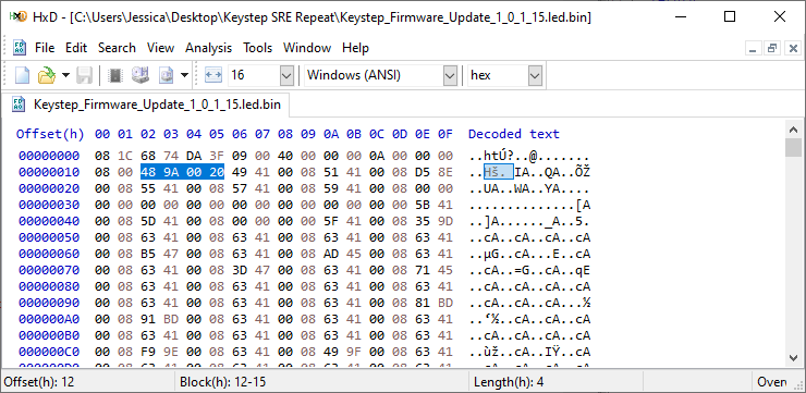
And after that, it’s all addresses that start with 0x0800, which is where interrupt handlers would
be in flash memory. Again, these addresses aren’t word aligned otherwise. It appears that our data
contains a header with some meta data. This would make sense, as the bootloader could use
information about data integrity and memory offsets when performing an update.
File Metadata
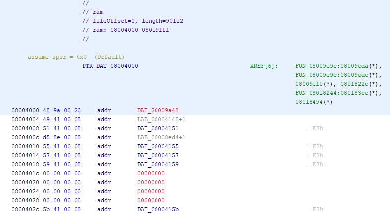
Let’s take a look at that 18 byte header:
08 1C 68 74 DA 3F 09 00 40 00 00 00 0A 00 00 00 08 00
The first four bytes also occur at 43 other points in the file, with very similar surroundings.
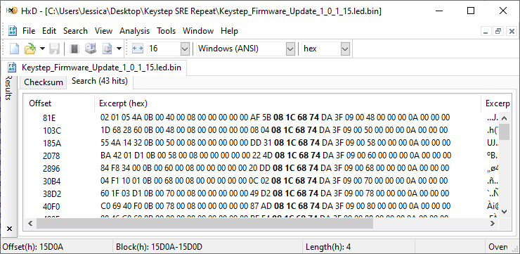
It looks like we have something that breaks the firmware into frames and then sends them one by
one. Moreover, the data to the left of the of the search term is also very structured, which leads
me to believe there may be a footer involved as well. Each one of these appears to be exactly
0x81E apart from one another as well. Let’s modify our python script to output each header.
header_start = bytes.fromhex("08 1C 68 74")
i = -1
while (i := chunk.find(header_start, i + 1)) >= 0:
    print(bytes.hex(chunk[i:i+18], " ", 1))
This gives:
08 1c 68 74 da 3f 09 00 40 00 00 00 0a 00 00 00 08 00
08 1c 68 74 da 3f 09 00 48 00 00 00 0a 00 00 00 08 00
08 1c 68 74 da 3f 09 00 50 00 00 00 0a 00 00 00 08 00
08 1c 68 74 da 3f 09 00 58 00 00 00 0a 00 00 00 08 00
...
It appears that the first seven bytes of the header are the same, followed by a counter that goes up by 8, and finally some zeros and two constants. Now, we know that each one of these was exactly the same distance apart, so I’m assuming at first that the last two bytes are the record size of the payload. The bootloader takes up the bottom of the flash memory, so I’m assuming that the counter is the memory offset of which to write the payload during an update and what the firmware’s memory location will be while in operation. We should then be able to extract the footer by looking at the bytes after the payload.
We can expand our parsing section to take a look at this footer as well as strip out the metadata to get our binary file:
header_start = bytes.fromhex("08 1C 68 74")
with open(fname + ".strip.bin", "wb") as out:
    i = 0
    while i < len(chunk):
        raw_header = chunk[i:i+18]
        header = struct.unpack(">7sh7sh", raw_header)
        i += 18

        rec_len = header[-1]
        out.write(chunk[i:i+rec_len])
        i += rec_len

        end = chunk.find(header_start, i + 1)
        footer = chunk[i:end]
        print("{} : {} : {}".format(bytes.hex(raw_header, " ", 1), rec_len,
                                    bytes.hex(footer, " ", 1)))
        i = end
We find that the footer is mostly static as well and has a fixed length, and the rest of the content
can just be concatenated together. This isn’t perfect: there’s still a different header type, but
it’s near the end of the file within the block of 255 characters, so we can go ahead with the
disassembly once more.
Final Disassembly
We can go ahead and remove the old binary file from the Ghidra project and import this newly
stripped one. Be sure to hit the “Options” button during the import and set the base address to the
correct 0x08004000:
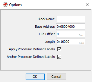
We can then open it and perform the analysis and (success!) we find way fewer errors than before. At the top of the file we can see our (now fixed) address table (press “P” on an entry to set the data type to a pointer).
The addresses are all off by one, which indicates that we are operating in “thumb” mode (default 16 bit instructions). Now, at this point we could jump into the code and start labelling everything that we can, but it’s a large file and we are looking for something specific.
Recall that the light is physically connected via the SPI2 data and clock pins. The datasheet (or
the peripheral library from before) contains its location in memory:
The magic number we are looking for is 0x40003800. It looks like it’s only directly twice in the
code. Nonetheless, we can apply a label make sure that it’s of a pointer type:

This function appears to pack the memory location into a structure with some other data, which is then referenced via pointers located in SRAM.
void FUN_08009614(void)

{
  undefined *puVar1;

  puVar1 = PTR_DAT_08009650;
  *(undefined **)PTR_DAT_08009650 = PTR_SPI2_BASE_0800964c;
  *(undefined4 *)(puVar1 + 4) = 0x104;
  puVar1 = PTR_DAT_08009650;
  *(undefined4 *)(PTR_DAT_08009650 + 8) = 0;
  *(undefined4 *)(puVar1 + 0xc) = 0;
  *(undefined4 *)(puVar1 + 0x10) = 0;
  *(undefined4 *)(puVar1 + 0x14) = 0;
  *(undefined4 *)(puVar1 + 0x18) = 0x200;
  *(undefined4 *)(puVar1 + 0x1c) = 0x18;
  *(undefined4 *)(puVar1 + 0x20) = 0;
  *(undefined4 *)(puVar1 + 0x24) = 0;
  *(undefined4 *)(puVar1 + 0x28) = 0;
  *(undefined4 *)(puVar1 + 0x2c) = 10;
  FUN_08008410();
  return;
}
This is a consequence of a hardware abstraction layer (HAL) being used to overlay the peripheral
memory locations and provide a standard interface between different chips. In the
STM32Cube library, we can find the definition
of an SPI_HandleTypeDef which is used to hold information about the SPI interface
(stm32f4xx_hal_spi.h:105).
typedef struct __SPI_HandleTypeDef
{
  SPI_TypeDef                *Instance;      /*!< SPI registers base address               */
  SPI_InitTypeDef            Init;           /*!< SPI communication parameters             */
  uint8_t                    *pTxBuffPtr;    /*!< Pointer to SPI Tx transfer Buffer        */
  uint16_t                   TxXferSize;     /*!< SPI Tx Transfer size                     */
  __IO uint16_t              TxXferCount;    /*!< SPI Tx Transfer Counter                  */
  uint8_t                    *pRxBuffPtr;    /*!< Pointer to SPI Rx transfer Buffer        */
  uint16_t                   RxXferSize;     /*!< SPI Rx Transfer size                     */
  __IO uint16_t              RxXferCount;    /*!< SPI Rx Transfer Counter                  */
  void (*RxISR)(struct __SPI_HandleTypeDef *hspi);   /*!< function pointer on Rx ISR       */
  void (*TxISR)(struct __SPI_HandleTypeDef *hspi);   /*!< function pointer on Tx ISR       */
  DMA_HandleTypeDef          *hdmatx;        /*!< SPI Tx DMA Handle parameters             */
  DMA_HandleTypeDef          *hdmarx;        /*!< SPI Rx DMA Handle parameters             */
  HAL_LockTypeDef            Lock;           /*!< Locking object                           */
  __IO HAL_SPI_StateTypeDef  State;          /*!< SPI communication state                  */
  __IO uint32_t              ErrorCode;      /*!< SPI Error code                           */
} SPI_HandleTypeDef;
This allows us to define the exact ordering and sizes of elements in the struct, which then can be displayed when we find pointers of that type. To add it to the workspace, we right click the file in the “Data Type Manager” and add a new struct. We can then fill out the constituent parts:
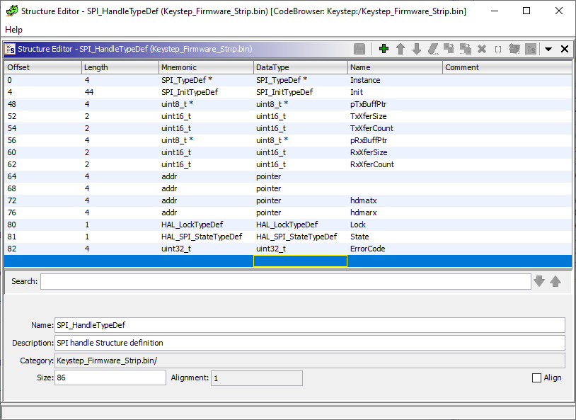
(I do believe there is some way to add the library header files to the project to avoid having to do this manually, but I just did it by hand as I couldn’t quite figure out how to work it.)
We can give our shared pointer and the functions nice names and the decompiled result is a lot easier to parse.
uint initialize_SPI2(void)
{
  SPI_HandleTypeDef *hspi;
  HAL_StatusTypeDef HVar1;

  hspi = PTR_hSPI2_08009650;
  PTR_hSPI2_08009650->Instance = PTR_SPI2_BASE_0800964c;
  (hspi->Init).Mode = 0x104;
  hspi = PTR_hSPI2_08009650;
  (PTR_hSPI2_08009650->Init).Direction = 0;
  (hspi->Init).DataSize = 0;
  (hspi->Init).CLKPolarity = 0;
  (hspi->Init).CLKPhase = 0;
  (hspi->Init).NSS = 0x200;
  (hspi->Init).BaudRatePrescaler = 0x18;
  (hspi->Init).FirstBit = 0;
  (hspi->Init).TIMode = 0;
  (hspi->Init).CRCCalculation = 0;
  (hspi->Init).CRCPolynomial = 10;
  HVar1 = HAL_SPI_Init(hspi);
  return (uint)HVar1;
}
We could use the header files to figure out what these constants are and label them as well, but we
can leave it as-is as were are more interested in the functions that are using this handler. Next,
we work outwards and identify the functions that use the handler. Some of these are just the
functions straight from the library. For example, this function at address 0x08008410:
HAL_StatusTypeDef HAL_SPI_Init(SPI_HandleTypeDef *hspi)
{
  HAL_StatusTypeDef HVar1;

  if (hspi == (SPI_HandleTypeDef *)0x0) {
    HVar1 = HAL_ERROR;
  }
  else {
    if (hspi->State == HAL_SPI_STATE_RESET) {
      HAL_SPI_MspInit(hspi);
    }
    hspi->State = HAL_SPI_STATE_BUSY;
    *(uint *)hspi->Instance = *(uint *)hspi->Instance & 0xffffffbf;
    *(uint32_t *)hspi->Instance =
         (hspi->Init).Mode | (hspi->Init).Direction | (hspi->Init).DataSize |
         (hspi->Init).CLKPolarity | (hspi->Init).CLKPhase |
         (uint)*(ushort *)&(hspi->Init).NSS & 0x200 | (hspi->Init).BaudRatePrescaler |
         (hspi->Init).FirstBit | (hspi->Init).CRCCalculation;
    *(uint32_t *)&hspi->Instance->CR2 = (hspi->Init).NSS >> 0x10 & 4 | (hspi->Init).TIMode;
    *(uint32_t *)&hspi->Instance->CRCPR = (hspi->Init).CRCPolynomial;
    *(uint *)&hspi->Instance->I2SCFGR = *(uint *)&hspi->Instance->I2SCFGR & 0xfffff7ff;
    *PTR_DAT_08008498 = 0;
    *(undefined4 *)((int)&hspi->ErrorCode + 2) = 0;
    hspi->State = HAL_SPI_STATE_READY;
    HVar1 = HAL_OK;
  }
  return HVar1;
}
can be found in stm32f4xx_hal_spi.c:313. We can identify HAL_GPIO_Init, the implementated
HAL_SPI_MspInit, and (most importantly) the HAL_SPI_Transmit functions in the same way. Only one
function calls HAL_SPI_Transmit (at address 0x080133e6), so we have the entry point for how the
lights are managed:
void LightControl_SendSPI(LightControl *ltctrl)
{
if (ltctrl->needsUpdate != 0) {
FUN_08012e70(ltctrl,0);
HAL_SPI_Transmit(ltctrl->hspi,<ctrl->displayByte,1,0x100);
FUN_08012e70(ltctrl,1);
ltctrl->needsUpdate = 0;
}
return;
}
This function is given a pointer to a struct that holds the SPI handler, what to display, and a flag
for if it needs to change what byte is currently being displayed. We can then make the
LightControl struct and fill out the fields from that reference. Walking up the callee functions,
we see that this pointer is stored in SRAM at address 0x200000a8, so we can give that a handle
name for the struct and find all of it’s references.
We can use the HardFault entry in the address table to find the function that is called when there
is an error. On this keyboard the four left-most lights just spin forever (same thing as happens in
bootloader mode).
And here is the matching function that handles this:
void LightControl_HardFaultLoop(void)
{
  uint local_8;

  LightControl_SetMaskBoth(*PTR_hltcntrl_0800c8f0,2,1);
  LightControl_SetMaskBoth(*PTR_hltcntrl_0800c8f0,7,1);
  LightControl_SetMaskBoth(*PTR_hltcntrl_0800c8f0,4,1);
  LightControl_SetMaskBoth(*PTR_hltcntrl_0800c8f0,3,1);
  do {
    local_8 = 0;
    while (local_8 < uint32_t_0800c8f4) {
      local_8 = local_8 + 1;
    }
    *DAT_0800c8f8 = *DAT_0800c8f8 + 1;
    LightControl_SendSPI(*PTR_hltcntrl_0800c8f0);
    LightControl_MaskLights(*PTR_hltcntrl_0800c8f0);
  } while( true );
}
We can also identify the code that causes the buttons to fade in when the keyboard is first started up.5
Next, we can identify the massive function at address 0x0800c16c as the main loop for the
program. It dispatches to functions that do just about everything, then runs the light update in the
last step before starting the loop over. Here, we can just look at the functions that reference the
light handler.
Next, we can open up the SysTick handler (0x08009d34) and see if contains any references to our
LightControl handle. The idea here is that the lights keep track of what part of the flash they
are on and it would either need to be updated here or in the main loop. It’s more natural to put it
in SysTick so the user interface doesn’t get slowed down if the main loop is doing more
work. There’s a few things happening here, but we do see it calls a function at 0x08013334 with
the handle.
void LightControl_TickInternal(LightControl *ltctrl)
{
  if (ltctrl->pShift1 != (undefined *)0x0) {
    if (ltctrl->tickGoal2 == '\n') {
      ltctrl->tickChangeFlag = 0;
    }
    else {
      if (ltctrl->tickFlag12 == 0) {
        if (ltctrl->currTick1 < ltctrl->tickGoal1) {
          ltctrl->currTick1 = ltctrl->currTick1 + 1;
        }
        else {
          ltctrl->currTick1 = 0;
          ltctrl->tickChangeFlag = 1;
          ltctrl->tickFlag12 = 1;
        }
      }
      else {
        if (ltctrl->currTick2 < ltctrl->tickGoal2) {
          ltctrl->currTick2 = ltctrl->currTick2 + 1;
        }
        else {
          ltctrl->currTick2 = 0;
          ltctrl->tickFlag12 = 0;
          ltctrl->tickChangeFlag = 1;
        }
      }
      if (ltctrl->tickChangeFlag != 0) {
        if (ltctrl->tickFlag12 == 0) {
          LightControl_ShiftHelper(ltctrl->pShift1,ltctrl->valShift1,1);
        }
        else {
          LightControl_ShiftHelper(ltctrl->pShift1,ltctrl->valShift1,0);
        }
      }
    }
  }
  return;
}
When we untangle this logic, we find that this changes a few internal flags based on counting up total tick events.
The LightControl structure also appears to a component that determines if the light is switched or
on or not before sending the byte to the SPI handler. I’ve referred to it as a “mask”, and it is
just a small array for each light of on and off times/counter values. At address 0x080131a4:
void LightControl_SetMask(LightControl *ltctrl,int Light,uint8_t aa,uint8_t bb)
{
  ltctrl->maskOnTime[Light] = aa;
  ltctrl->maskOffTime[Light] = bb;
  ltctrl->cc[Light] = *(uint16_t *)PTR_DAT_080131c0;
  return;
}
Then, this function (0x08013230) is called which determines if the light is actually on or not
based on those counters.
void LightControl_MaskLights(LightControl *pLParm1)
{
  ushort uVar1;
  uint Light;
  uint uVar2;

  uVar1 = *PTR_DAT_080132bc;
  uVar2 = (uint)uVar1;
  Light = 0;
  while (Light < 8) {
    if (uVar1 == 0xffeb) {
      *PTR_DAT_080132bc = 0;
      pLParm1->cc[Light] = 0;
    }
    if ((pLParm1->maskOnTime[Light] != 0) && ((uint)pLParm1->cc[Light] != uVar2)) {
      if ((uint)pLParm1->maskOnTime[Light] + (uint)pLParm1->cc[Light] == uVar2) {
        LightControl_SetLight(pLParm1,Light,1);
      }
      if ((uint)pLParm1->maskOffTime[Light] +
          (uint)pLParm1->cc[Light] + (uint)pLParm1->maskOnTime[Light] == uVar2) {
        LightControl_SetLight(pLParm1,Light,0);
        pLParm1->cc[Light] = uVar1;
      }
    }
    Light = Light + 1 & 0xff;
  }
  return;
}
With the actual light bits saved using (0x080131c4)
void LightControl_SetLight(LightControl *ltctrl,int Light,int Value)
{
  if (Value == 0) {
    ltctrl->displayByte = ltctrl->displayByte & ~(byte)(1 << Light);
  }
  else {
    ltctrl->displayByte = ltctrl->displayByte | (byte)(1 << Light);
  }
  ltctrl->needsUpdate = 1;
  return;
}
Finally, we can identify all the functions that update the mask, meaning that they want the
visibility to be controlled by an independently ticking timer (which looks to be located at
0x20000070). In particular, we want to find ones that set the mask for the specific bits
corresponding to the octave buttons, as some of the others might use a similar flashing
process. Note that the light is defaulted to “on” when the mask on time is set to 0.
There are only a handful of functions that change the state of the mask, so it is relatively easy to
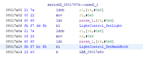
check them all manually. In particular, we find this very interesting function (0x08017966):
void LightControl_SetOctaveLights(OctaveParams *param_1)
{
  switch(*(undefined *)param_1) {
  case 0:
    LightControl_SetLight(param_1->hlightcntl,(uint)param_1->field_0x9,1);
    LightControl_SetLight(param_1->hlightcntl,(uint)param_1->field_0x8,1);
    LightControl_ResetMask(param_1->hlightcntl,(uint)param_1->field_0x9);
    LightControl_ResetMask(param_1->hlightcntl,(uint)param_1->field_0x8);
    break;
  case 1:
    LightControl_SetLight(param_1->hlightcntl,(uint)param_1->field_0x8,0);
    LightControl_SetMaskBoth(param_1->hlightcntl,(uint)param_1->field_0x8,6);
    break;
  case 2:
    LightControl_SetLight(param_1->hlightcntl,(uint)param_1->field_0x8,0);
    LightControl_SetMaskBoth(param_1->hlightcntl,(uint)param_1->field_0x8,4);
    break;
  case 3:
    LightControl_SetLight(param_1->hlightcntl,(uint)param_1->field_0x8,0);
    LightControl_SetMaskBoth(param_1->hlightcntl,(uint)param_1->field_0x8,2);
    break;
  case 4:
    LightControl_SetLight(param_1->hlightcntl,(uint)param_1->field_0x8,0);
    LightControl_SetMaskBoth(param_1->hlightcntl,(uint)param_1->field_0x8,1);
    break;
  case 0xfc:
    LightControl_SetLight(param_1->hlightcntl,(uint)param_1->field_0x9,0);
    LightControl_SetMaskBoth(param_1->hlightcntl,(uint)param_1->field_0x9,1);
    break;
  case 0xfd:
    LightControl_SetLight(param_1->hlightcntl,(uint)param_1->field_0x9,0);
    LightControl_SetMaskBoth(param_1->hlightcntl,(uint)param_1->field_0x9,2);
    break;
  case 0xfe:
    LightControl_SetLight(param_1->hlightcntl,(uint)param_1->field_0x9,0);
    LightControl_SetMaskBoth(param_1->hlightcntl,(uint)param_1->field_0x9,4);
    break;
  case 0xff:
    LightControl_SetLight(param_1->hlightcntl,(uint)param_1->field_0x9,0);
    LightControl_SetMaskBoth(param_1->hlightcntl,(uint)param_1->field_0x9,6);
  }
  return;
}
We have our function that controls the octave keys flashing! This function splits on some value and
sets a light and mask accordingly. For the “0” case it shuts off the light and clears the mask, and
for every other case it turns the light on and sets the flashing amount to either 1, 2, 4, or
6 in two different ways. Since the mask defaults to on, all we have to do is update the literal in
the calls to LightControl_SetMaskBoth to 0. Here we can see that the 6 in the second is placed
in the register by a single mov:
We change this parameter to zero in eight spots and we are done!
Reassembly
This type of patch is ideal because we don’t need move around any instructions around in the file, we can simply overwrite where they occur in the file. We can head back to the python script again and write a quick replacement procedure based on a given memory address.
chunk_updated = bytearray(chunk)
patch_addresses = [(0x08017a0c, 6, 0), (0x08017a22, 4, 0),
                   (0x08017a38, 2, 0), (0x08017a4e, 1, 0),
                   (0x0801798e, 1, 0), (0x080179a4, 2, 0),
                   (0x080179ba, 4, 0), (0x080179d0, 6, 0)]
for addr, a, b in patch_addresses:
    header_count = (addr - mem_start) // 2048 + 1
    patch_index = (addr - mem_start) + 18 * header_count + 12 * (header_count - 1)
    print(bytearray.hex(chunk_updated[patch_index - 4:patch_index + 4], " ", 1), end="")
    print("\t\t->\t\t", end="")
    assert(chunk_updated[patch_index] == a)
    chunk_updated[patch_index] = b
    print(bytearray.hex(chunk_updated[patch_index - 4:patch_index + 4], " ", 1))

with open(fname + ".patched.led", "w") as out:
    out.write(bytearray.hex(chunk_updated).upper())
We can then attempt to upgrade the keyboard with the patched firmware using the MIDI Control Center and we get the following dialog:
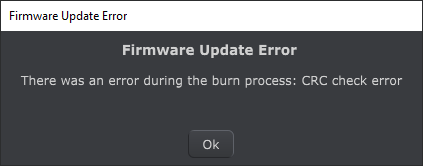
We’ve neglected to update some parts of the file that have to do with data integrity and the updater rejected it before even sending it on to the keyboard. The only place this can be stored is in the frame information and there are only two bytes in the footer that are non-relatively constant.
I was stuck here for quite some time. The dialog implied that I needed a
CRC algorithm, but there are many that can
possibly be a two byte result. I ended up using the python library crccheck and testing the whole
suite of them, as well as looking at how the internal ARM CRC methods worked. After getting nowhere
for a while, I realized that I’ve using a disassembler up to this point, so why not disassemble the
MIDI control center?
The control center is mostly one large executable, so it’s a matter of adding it to our Ghidra project and letting it perform the analysis. This file is quite a bit bigger, but we have the exact string in the dialog to perform a search on. We find this string:
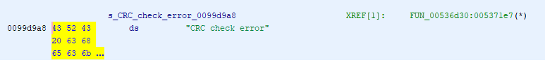
Which then is referenced in this function:
          if ((ushort)((short)local_c8 +
                      (ushort)*(byte *)((int)currBytePointer + 1) * 0x100 +
                      (ushort)*(byte *)currBytePointer) != 0) {
            FUN_00703040("CRC check error");
            FUN_006ee960();
            LOCK();
            iVar13 = _DAT_fffffff8 + -1;
            bVar18 = _DAT_fffffff8 == 0;
            _DAT_fffffff8 = iVar13;
            if (bVar18) {
              _DAT_fffffff8 = iVar13;
              thunk_FUN_008765bb(0xfffffff8);
            }
            FUN_008765bb(local_88);
            local_8 = 3;
            goto LAB_00537844;
          }
The actual calculation of the checksum (local_c8) is done in assembly around here:
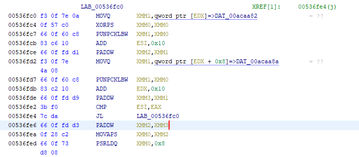
I would ignore the decompiled version of this operation, as these vectorized instructions tend to
get turned into a horrible mess of bitwise operations by the tool. As it turns out, the “CRC check”
is just the sum of all the previous bytes except the first two bytes in the head, inverted, and
truncated into a 16-bit int. We can confirm this using our parsing script.
seg   1 - 8004000        08 1c 68 ... : (2048) : ... 00 af 5b    AF 5B
seg   2 - 8004800        08 1c 68 ... : (2048) : ... 00 08 04    08 04
seg   3 - 8005000        08 1c 68 ... : (2048) : ... 00 dd 31    DD 31
seg   4 - 8005800        08 1c 68 ... : (2048) : ... 00 22 4d    22 4D
seg   5 - 8006000        08 1c 68 ... : (2048) : ... 00 20 dd    20 DD
...
Comparing with another firmware version, it appears that there also is another checksum at the very end of the file that is within the program memory itself.
...
FF FF FF FF FF FF FF FF FF FF FF FF FF FF FF FF
FF FF FF FF FF FF FF FF FF FF FF FF FF FF 64 00    <- These two bytes here
0B 01 B0 00 08 00 0D 01 B0 00 00 00 0E 01 B0 00
00 00 00 00 00 00 98 04
end
Which means we have three checksums to update: the one for the block containing the changed instructions, the one at the end of the program, and lastly the one for the block that contains the whole program checksum.
We can do a little bookkeeping to keep each segment in a namedtuple and then perform the packing
and rechecksumming as necessary:
def calc_checksum(segment):
    checksum = sum(struct.pack(">7sH7sH", *segment.header)[2:])
    checksum += sum(segment.data)
    checksum += sum(segment.footer.p1)
    return 0x10000 - (checksum & 0xffff)

mem_offset = 0x08004000
patch_addresses = [(0x08017a0c, 6, 0), (0x08017a22, 4, 0),
                   (0x08017a38, 2, 0), (0x08017a4e, 1, 0),
                   (0x0801798e, 1, 0), (0x080179a4, 2, 0),
                   (0x080179ba, 4, 0), (0x080179d0, 6, 0)]
for addr, a, b in patch_addresses:
    header_index = (addr - mem_offset) // 2048
    s = segments[header_index]
    patch_index = addr & 0x3FF
    assert(s.data[patch_index] == a)
    s.data[patch_index] = b
    checksum = calc_checksum(s)
    segments[header_index] = Segment(s.header, s.data,
                                     Footer(s.footer.p1, checksum))

outdata = bytes(b"".join(s.data for s in segments))
total = (0x10000 - sum(outdata[:-2]) & 0xffff)

segments[-1].data[-2] = total % 256
segments[-1].data[-1] = total // 256
checksum = calc_checksum(segments[-1])
segments[-1] = Segment(segments[-1].header, segments[-1].data,
                       Footer(segments[-1].footer.p1, checksum))
And lastly rewrite everything back out into a flat file (there’s some slight weirdness with the endian-ness between the header and the footer as the address offset appears to be big-endian while the checksum is little-endian).
with open(fname + ".patched.led", "w") as out:
    for s in segments[:-1]:
        out.write(bytes.hex(struct.pack(">7sH7sH", *s.header)).upper())
        if s.footer:
            out.write(bytearray.hex(s.data).upper())
            out.write(bytes.hex(struct.pack("<10sH", *s.footer)).upper())
    out.write(bytes.hex(struct.pack(">7sH7sH", *segments[-1].header)).upper())
    out.write(bytearray.hex(segments[-1].data).upper())
    out.write(bytes.hex(struct.pack("<22sH", *segments[-1].footer)).upper())
We can now take our newly patched firmware and successfully install it on the keyboard! No more flashing octave button!
Final Thoughts
This was an interesting project to tackle because the discovery had to happen “bottom-up” from the raw peripheral locations. Because the user interface of a keyboard is mostly buttons and lights, there were only two strings found in the entire firmware (which I assume were related to USB identifiers). The entirety of the code is sloshing data around between systems based on some global counters. I never did find where the MIDI messages were constructed, as the sequences in the spec are short groups of bytes that were impossible to search for. The peripheral memory locations were pretty much unique, which allowed for easy identification.
Ideally, I would have liked to add some intermittent blinking to the “Transpose” and “Kbd Play” states so that they could be distinguished from the constant lights when holding “Shift”, but there were no masks defined for those states and it would be much more involved to add that functionality.
As complicated as this process was, this whole project barely scratched the surface of what could potentially be done with a custom firmware. The upgrade process is the raw machine code with some added headers, so any firmware could be written and loaded on the device. For instance, it is possible to add other arpeggiator modes (like “thumb down”) or change the pitch bend to a second mod source (or all of the controls to mod sources for that matter). You could write a rickroll firmware that just plays a song over and over when it is connected.
Major props to Artuira for making a device that is actually user-modifiable. The case wasn’t glue shut or use obscure screws, and the update process was open enough for this to actually be done. I had wanted to do a similar project to modify my wi-fi scale to report to my personal server and I discovered that it was completely locked down from end-to-end. I much prefer to focus on delivering good hardware rather than getting tied to an ecosystem.6
I’m planning on taking a look at my KeyLab Essential next (more specifically how the pads work when it is not in “User” mode). This will likely be more involved as it does look like it does more communication via the PC driver rather than communicating purely through MIDI.
You can find the source code for the firmware parser here.
-
I understand that this is fixed on the latest firmware, but this process started around April 2019. ↩
-
Also shameless plug for IFixit’s screwdrivers. ↩
-
On that note, I wonder if that is the reason the KeyStep has exactly 8 lights and buttons: to correspond with specific commodity chips? ↩
-
You can find a copy of it here, but beware it is a hefty 900 pages or so. ↩
-
I didn’t get into too much detail on this before, but there is another pin on the chip that controls the brightness using a PWM. I assume this is connected to a gate that grounds out all of the LEDs, but I didn’t investigate it further as that is not what we’re interested in at the moment. ↩
-
Check out right to repair for more information. ↩